I had hoped that my gate monitoring and power system would be adequate, but it wasn’t. I was having to swap out the gate battery for a charged one every two to three days, which meant that it was inevitable that at some point the gate would be dead when we needed it. In addition, the actual battery swap operation was a difficult one, involving tight-fitting connections that mixed heavy-gauge wire for power transport with tiny wires for the monitoring circuitry all ground together in wirenuts. Pulling hard enough to disconnect the battery often resulted in one of the finer wires coming out of a wirenut, leading to stoop labor to repair it and necessitating the use of colorful vocabulary.
The problem is that mains power (from our solar plant) is only available on the opposite side of the driveway from the gate controller. I don’t want any more overhead cables nor any trenching under the newly graveled drive. It’s way too shady anywhere around the gate to effectively deploy the little solar panel that came with the gate.
I considered fashioning four copper contacts that would connect a charger circuit from the garage to the gate controller when the gate was closed, but copper exposed to the elements and subject to mechanical wear and precise alignment seemed fraught.
I thought about adapting inductive charging technology so a powered loop on the garage side of the gate would induce current that could charge the battery when the gate was closed, using something like this induction power system but, wow, we’re getting pretty complicated here.
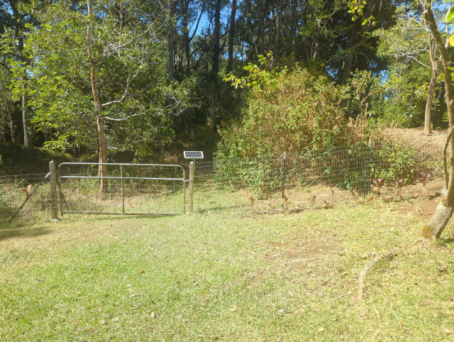
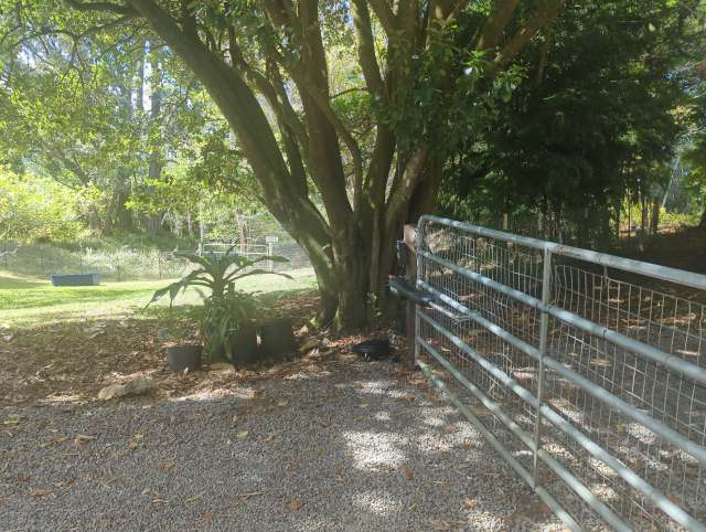
What I’ve actually done is to use wire I had left over from the landscape lighting project to move the solar panel from off the gate, where it only got direct sun about two hours a day (weather permitting), to a place (near the “upper gate”) with at least the potential for 10 hours or so of direct sun a day. Here’s the view from the main gate to the upper gate, showing the solar panel. It’s about 100 feet of wire, but I don’t think the loss will be significant (at least on sunny days).
Yes, there’s a panel by a gate that has to be manually opened, but that’s where the light is.
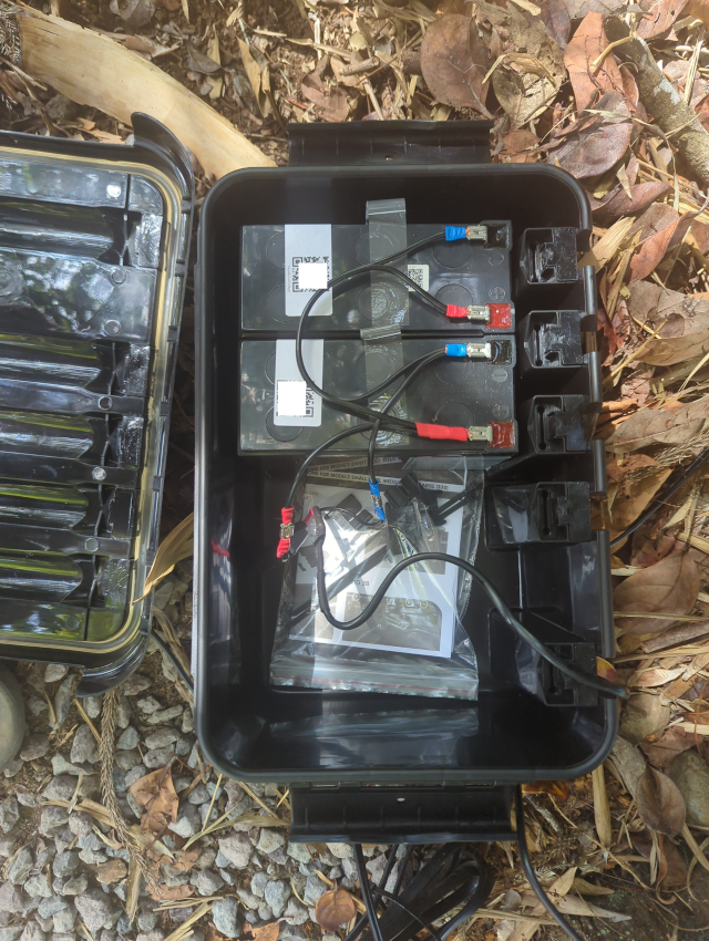
I also used the larger of the two weatherproof boxes I bought to change to having two batteries in parallel, doubling the power capacity. While I was re-wiring the batteries, I simplified the connections to make it easier to charge in-the-box just in case HA needs to do that. Asking her to manage an actual battery swap would be a bit much, unless and until I invest the time and money to put in actual fit-for-purpose connectors.
While I was re-wiring, I took out the WiFi monitoring board. Sigh. It was a beautiful, simple, and effective solution except that powering a WiFi radio used almost a full watt of power, which was contributing to the rapid demise of the batteries.
Let’s see, the batteries are about 7 amp-hours at 12 volts, so 84 watt-hours. That’s about 3½ days of runtime just powering the monitor so it’s not surprising I was only getting three days out of a charge. (Yeah, I should have done that math before wiring the thing up, by I was seduced by the promise of a direct WiFi connection.)
The new battery box is much simpler.
I’m hoping that there will be enough solar charging that we’ll not have to worry about the battery charge, but I will likely come up with a remote monitoring solution using a 900 MHz system such as the one I’m using to monitor the hot tub temperature, the brooding box temperature, and the freezer temperature. Those radio transmitters will run for many months on a pair of AA batteries, so should be much less intrusive for monitoring the gate power. Alas, I haven’t found a remote voltmeter as simple as the Shelly Uni Plus board but that uses a more efficient UHF radio link. I’m sure one exists, or I could always roll my own.
For now, I’m just going to run this setup for a few days and stick my multimeter on the batteries to see how they’re doing.
—2p